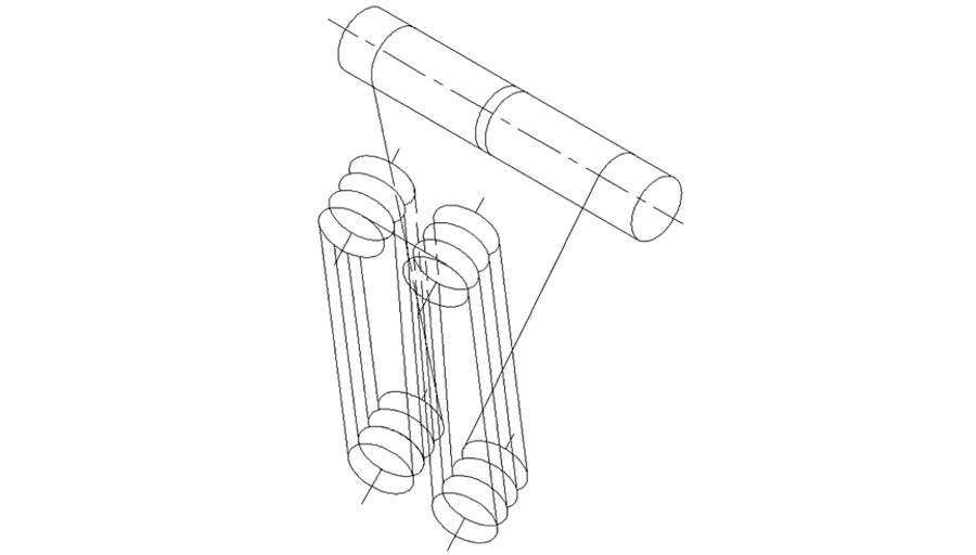
In a project, the installer's understanding of the wire rope winding path in the crane trolley drawings was different from that of the designer. So what aspects need to be paid attention to when drawing a crane wire rope winding diagram? The following figure is a winding diagram of the hoisting mechanism of an overhead crane owner, with a dense line in the same direction and cross-blocking, which is difficult to understand.
In crane design and installation, the winding path of the wire rope is crucial. Clearly and accurately expressing the winding path ensures equipment stability and safety and helps construction personnel understand the drawings, avoiding misunderstandings and operational errors.
Key Points for Drawing Wire Rope Winding Diagrams
Choose the Right Viewing Angle Different view orientations can help the operator fully understand how the wire rope goes around the pulley, pulley, or other components.
Use Colors and Line Styles to Differentiate Paths In the drawing, different wire rope segments are distinguished by different colors or line types, especially if there are multiple winding paths intertwined. For example, you can use a solid line to represent the front path of a wire rope and a dashed line to represent its rear path.
Clearly Label Paths and Directions Each wire rope segment should be clearly marked, including the start point, end point, and each drum or pulley through which it passes. Arrows can be added to the diagram to indicate the direction of movement of the wire rope.
Label Joint Positions Joint Identification: Specifically label the joint positions of the wire rope and note the type and layout of the joints. Avoid High-Load Areas: Ensure joints are not located in high-load areas to reduce safety risks.
Layered Representation for Multi-Layer Winding Hierarchical Display: Use layered or sectional views to show the winding relationship between inner and outer layers. Local Details: Use local views to display details of complex multi-layer winding sections.
Use Legends and Symbols Partial view: For multi-reel or complex winding mechanism, the winding method of a certain section of wire rope is specifically indicated, which helps the reader to understand the role of each section and the interrelationship between multiple sections.
Label Materials and Specifications Material Information: Note the material, specifications, and performance parameters of the wire rope in the drawing's detail section. Load and Safety Factor: Label the working load and safety factor of the wire rope, helping construction personnel assess the equipment's safety.
Indicate Wear-Prone Areas Wear Identification: Label wear-prone areas near pulleys or guide devices to remind construction personnel to perform regular inspections and maintenance.
In addition, the workload and safety factor can be indicated, and areas prone to wear and tear can also be indicated on the diagram, especially near pulleys or guides. This helps with regular maintenance and inspections.
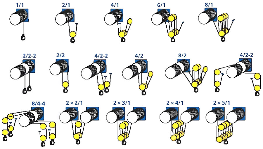
Attached are some commonly used wire rope winding magnification charts for reference:
When drawing crane wire rope winding diagrams, clearly and accurately expressing the path is crucial to ensuring the safe operation of the equipment. By choosing the right viewing angle, using colors and line styles to differentiate paths, clearly labeling key information, and optimizing drawing expression, construction efficiency can be significantly improved, reducing misunderstandings and operational errors. As a crane manufacturer, we are committed to providing high-quality design and construction support to ensure every piece of equipment operates safely and efficiently.